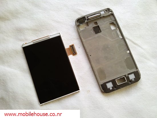
ၿဖဳတ္ရန္ လိုအပ္ ေသာ ပစၥည္းမ်ား : Phillips screwdriver, plastic tool such as a guitar plectrum or credit card.
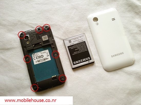
- Remove your back cover, battery, sim and memory card. Then remove the seven screws you can see, circled below.
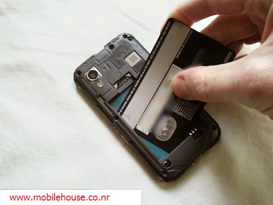
- Next, slide something thin and flat into the battery compartment, as shown below. This will release the battery compartment.
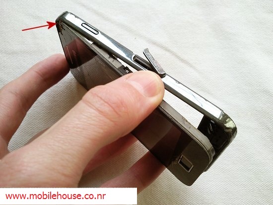
- Lift the battery compartment from the bottom and then lift it over the corner indicated by the arrow. A little force is required.
- With the battery compartment removed, your phone should look like below. A ribbon connector, circled below, needs to be disconnected. This attaches like a plug and socket. Just lever it up to unplug. On the left and right side of the phone are the power and volume switches. These are permanently connected to the circuit board but are stuck to the side of the housing with double sided tape. Carefully peel them away from the side of the housing, leaving them connected to the circuit board. The mic, indicated by the arrow at the bottom of the phone, is attached in the same way and also needs to be lifted away from the housing.
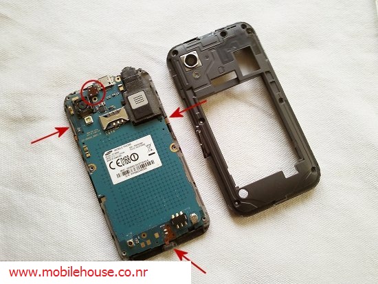
- With the ribbon disconnected and the power, volume button and mic lifted away from the housing, your phone should look like below.
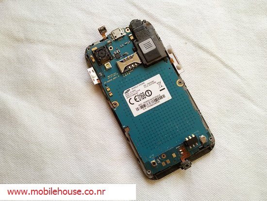
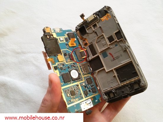
- Lift the circuit board from right to left and you'll see it's still attached to the phone by another ribbon, circled in the photo below. Again, this attaches like a plug and socket and can be levered away from the circuit board.
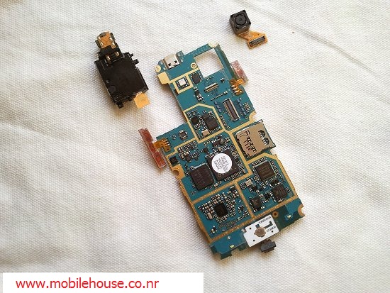
- The circuit board should now be free, as shown below. The ribbon connectors for the camera and jack socket are circled below. Again, these attach like a plug and socket and can be levered away from the circuit board.
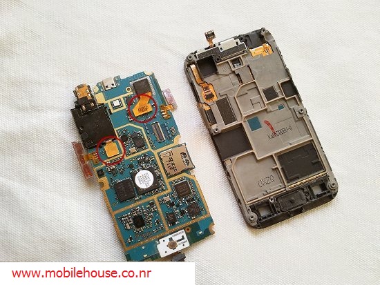
- Below you can see the camera and jack socket once they have been removed.
- The next stage is to disconnect the ribbon which comes from the touch screen/digitizer. See the next stage for details.
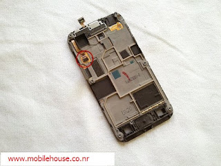
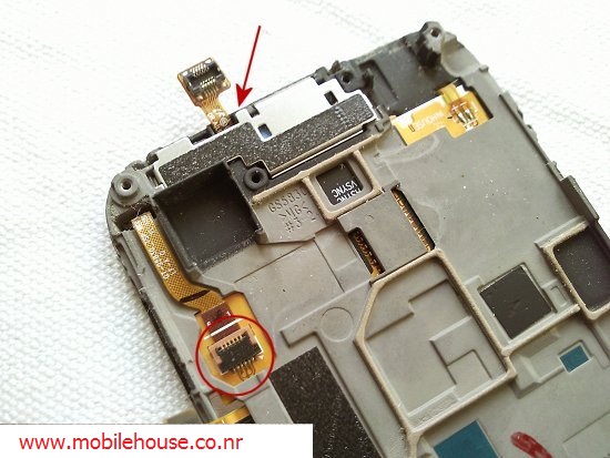
- Circled below is a close up of the ribbon cable which is attached to the touch screen/digitizer. This ribbon connects in a different way to the last few and is called a zif connector. The black part is a latch that opens and closes on a hinge. Carefully lift it up, towards the ribbon and the ribbon will be free. Refer to the next stage to see the latch in the open position. The auto rotate sensor and earpiece are indicated by the arrow. Lever this from the point shown to remove it.
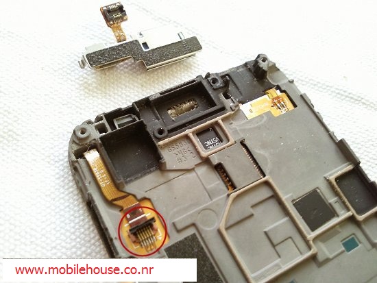
- Below you can see the connector in the open position and the ribbon is now free. The auto rotate sensor and earpiece have now also been removed.
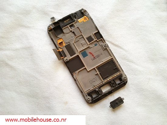
- Tip the phone over and the home button and gasket for the auto rotate sensor will fall out.
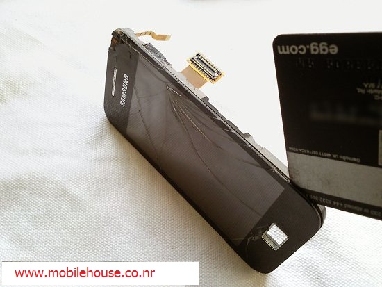
- To remove the touch screen you first need to heat all the way around the edge of the screen with a hot air gun or hair dryer. Do this for about 60 seconds and the adhesive holding the screen in place will loosen. Next, run something like the edge of a credit card around the very edge (the black part) of the screen. Carefully go all the way around the edge of the screen until it is released.
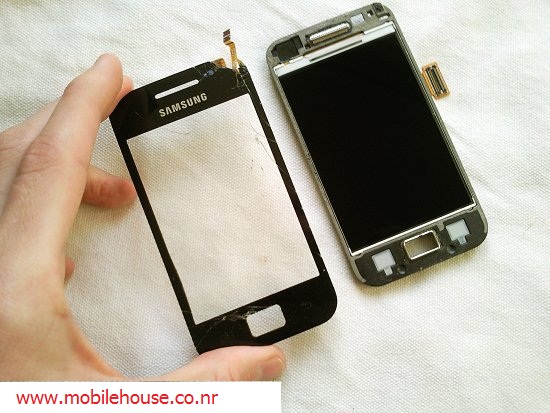
- With the touch screen/digitizer removed, your phone should look like below.
- Turn the phone over and push the back of the LCD screen from the point shown. This will raise it enough on the other side for you to slide your plastic tool underneath the LCD screen.
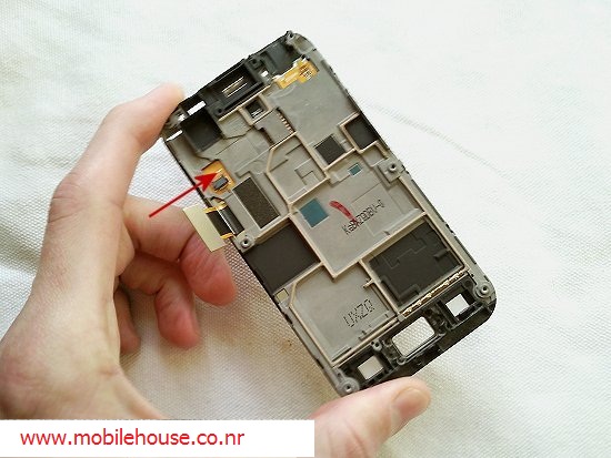
- Slide your plastic tool under the left side of the LCD screen to release it. Do not apply force and do not lever the screen.
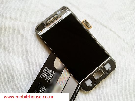
- You should now have the LCD screen removed, as shown below. Disassembly is now complete. Reverse the whole procedure for reassembly.
